
 Canadian Dollars


Guaranteed Fitment
Always the correct part


have questions?
Always the correct part
We know our products
Fast & Reliable


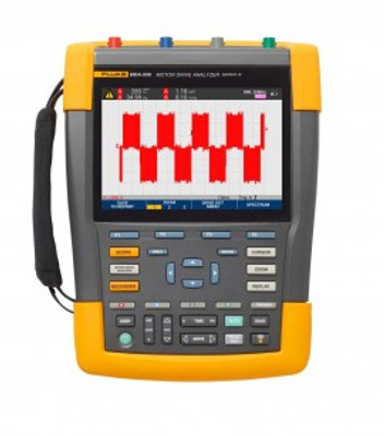
Save time and eliminate the hassle of setting up complex measurements with the drive analyzer that simplifies the troubleshooting process. Select a test, and the step-by-step guided measurements will locate where to make voltage and current connections. The preset measurement profiles will capture all the data necessary for each critical motor-drive section—from the input to the output, the DC bus, and the motor itself.
Features
Applications
Drive Input
Measure input voltage and current to quickly see whether values are within acceptable limits by comparing the drive's nominal rated voltage to the actual supplied voltage. Then, check the input current to determine if the current is within the maximum rating and the conductors are suitably sized. You can also check whether the harmonic distortion is within an acceptable level by visually inspecting the waveform shape or by viewing the harmonics spectrum screen which shows both the total harmonic distortion and individual harmonics.
Voltage and Current Unbalance
Check the voltage unbalance at the input terminals so you can ensure the phase unbalance is not too high (>6 to 8%), and that the phase rotation is correct. You can also check the current unbalance, as excessive unbalance may indicate a drive rectifier problem.
Extended Harmonic Measurements
Excessive harmonics are not just a threat to your rotating machines but also to other equipment connected to the electrical power system. It provides the ability to discover the harmonics of the motor-drive but can also discover the possible effects of inverter switching electronics. It has three harmonic ranges, 1st to 51st Harmonics, 1 to 9 kHz and 9 to 150 kHz giving the ability to detect any harmonic pollution problems.
DC Bus
In a motor-drive the conversion of AC to DC inside the drive is critical, having the correct voltage and adequate smoothing with low ripple is required for the best drive performance. High ripple voltage may be an indicator of failed capacitors or incorrect sizing of the connected motor. The record function can be used to check DC bus performance dynamically in the operating mode while a load is applied.
Drive Output
Check the output of the drive focusing both on voltage to frequency ratio (V/F), and voltage modulation. When high V/F ratio measurements are experienced, the motor may overheat. With low V/F ratios, the connected motor may not be able to provide the required torque at the load to sufficiently run the intended process.
Voltage Modulation
Measurements of the Pulse Width Modulated signal are used to check for high voltage peaks which can damage motor winding insulation. The rise time or steepness of impulses is indicated by the dV/dt reading (rate of voltage change over time), this should be compared to the motor's specified insulation. The measurements can also be used to measure switching frequency to identify whether there is a potential issue with electronic switching, or with grounding, where the signal floats up and down.
Motor Input
Ensuring that voltage is being supplied at the motor input terminals is key, and the selection of cabling from drive to the motor is critical. Incorrect cabling selection can result in both drive and motor damage due to excessive reflected voltage peaks. Checking that the current present at the terminals is within the motor rating is important as over current condition could cause the motor to run hot, decreasing the life of the stator insulation which can result in the early failure of the motor.
Motor Shaft Voltage
Voltage pulses from a variable speed drive can couple from a motor's stator to its rotor, causing a voltage to appear on the rotor shaft. When this rotor shaft voltage exceeds the insulating capacity of the bearing grease, flashover currents (sparking) can occur, causing pitting and fluting of the motor bearing race, damage that can cause a motor to fail prematurely. It is supplied with carbon fiber brush probe tips that can easily detect the presence of destructive flashover currents, while the impulse amplitude and count of events will enable you to take action before failure occurs. The addition of this accessory and capability of the MDA-550 allows you to discover potential damage without investing in expensive permanently installed solutions.
Step-by-Step Guided Measurements Ensure You Have the Data You Need, When You Need It
Designed to help you quickly and easily test and troubleshoot typical problems on three-phase and single-phase inverter type motor-drive systems. The on-screen information, and step-by-step setup guidance make it easy to con- figure the analyzer and get the drive measurements you need to make better maintenance decisions, fast. From power input to the installed motor, it provides the measurement capability for the fastest motor-drive troubleshooting.
Reporting and Analysis
Simplifies the process of gathering data and writing test reports with a built-in report generator. At each test point or measurement there is the option to create, update or modify a report. Simply press ‘SAVE TO REPORT' and select the appropriate screens to save into a text based report file. By performing the step-by-step guided measurements a comprehensive report can be created directly from the instrument to document the entire troubleshooting process. Input the report name. The single report encompasses all recorded measurements and can easily be shared with other users and used for motor- drive benchmarking, and for comparing data now and in the future.
Using Fluke Thermal Imaging to Troubleshoot Motors & DrivesInfrared cameras, also called thermal imagers, are useful for troubleshooting motor problems as well as for monitoring motor condition for preventative maintenance in power generation, manufacturing and commercial plants. Thermal images of motors reveal their operating condition as indicated by surface temperature. Such condition monitoring is important as a way to avert many unexpected motor malfunctions in systems that are critical to manufacturing. The onset of motor failures can often be detected by a variety of techniques, including vibration, ultrasound and thermal imaging.
In this article, we cover why use thermal imaging and what to scan, as well as some notes on what to look for, including shaft misalignment.
Facilities Maintenance Challenges and the Fluke SolutionsFacilities maintenance professionals face a wide range of challenges, from electrical and mechanical equipment uptime to overall safety concerns. It’s critical to maintain facilities and the associated assets at peak performance. Let's review the issues faced by maintenance managers, IT support, and electrical/mechanical technicians. Along with the Fluke solutions that offer to save you time and money while increasing efficiency and safety. Fluke makes reliable, rugged and accurate tools to maintain electromechanical systems, motors, pumps, electrical distribution systems and more to keep your world up and running.
| DC Voltage (V DC) | |
| Maximum Voltage with 10:1 or 100:1 Probe | 1000 V |
| Maximum Resolution with 10:1 or 100:1 Probe | 1 mV |
| Full Scale Reading | 999 counts |
| Accuracy at 4 s to 10 us/div | ±(3% + 6 counts) |
| AC Voltage (V AC) | |
| Maximum Voltage with 10:1 or 100:1 Probe | 1000 V |
| Maximum Resolution with 10:1 or 100:1 Probe | 1 mV |
| Full Scale Reading | 999 counts |
| 50 Hz | ±(3% + 10 counts) - 0.6% |
| 60 Hz | ±(3% + 10 counts) - 0.4% |
| 60 Hz to 20 kHz | ±(4% + 15 counts) |
| 20 kHz to 1 MHz | ±(6% + 20 counts) |
| 1 MHz to 25 MHz | ±(10% + 20 counts) |
| True-RMS Voltage (V AC+DC) | |
| Maximum Voltage with 10:1 or 100:1 Probe | 1000 V |
| Maximum Resolution with 10:1 or 100:1 Probe | 1 mV |
| Full Scale Reading | 1100 counts |
| DC to 60 Hz | ±(3% + 10 counts) |
| 60 Hz to 20 kHz | ±(4% + 15 counts) |
| 20 kHz to 1 MHz | ±(6% + 20 counts) |
| 1 MHz to 25 MHz | ±(10% + 20 counts) |
| Peak Voltage (V Peak) | |
| Modes | Max peak, min peak, or pk-to-pk |
| Maximum Voltage with 10:1 or 100:1 Probe | 1000 V |
| Maximum Resolution with 10:1 or 100:1 Probe | 10 mV |
| Max/Min Peak | ±0.2 division |
| Pk-to-Pk | ±0.4 division |
| Full Scale Reading | 800 counts |
| Frequency (Hz) | |
| Range | 1.000 Hz to 500 MHz |
| Full Scale Reading | 999 counts |
| Accuracy | ±(0.5% + 2 counts) |
Everything you need to know about orders, cancellations, refunds, and delivery.
EquipTestPro ships to both Canada and the United States. We are pleased to serve customers across North America with reliable, trackable delivery options.
When you place an order, a flat-rate shipping charge will be applied at checkout based on your order. The applicable rate will be clearly displayed before you complete your purchase.
Flat-rate shipping is calculated to reflect the cost of reliable, insured delivery. The rate shown at checkout is final — no hidden surcharges will be added after your order is placed.
For certain items, shipping costs are calculated based on the weight of the product. The weight of any weight-based item is listed on its product detail page.
For example, an item weighing 3.2 lbs will be rated at 4 lbs for shipping calculation purposes. This policy is standard practice across all major carriers we work with.
Some products sold on EquipTestPro are subject to shipping restrictions due to regulatory, carrier, or safety requirements. These include but may not be limited to:
Where restrictions apply, this will be clearly noted on the product listing. If you have questions about a specific product's shipping eligibility to your location, please contact us before placing your order.
Orders are processed on business days (Monday through Friday, excluding statutory holidays). Orders placed after business hours or on weekends will begin processing the following business day.
You are entitled to cancel your Order within 30 days of receipt without providing a reason, subject to the processing fee structure described below.
The cancellation deadline is 30 days from the date on which you received the Goods, or on which a third party appointed by you (other than the carrier) takes possession of the delivered product.
To exercise your cancellation right, notify us with a clear written statement by:
The following fee structure applies to all cancellations. Please review carefully before requesting a cancellation.
A processing fee of 10% of the total order value will be withheld from your refund to cover payment processing, handling, and administrative costs.
If we cancel your order due to item unavailability, no processing fee will be withheld. You receive a full refund of the amount paid.
Refunds will be issued using the same payment method as the original purchase. No additional fees beyond those described above will be applied.
To be eligible for a return, all of the following conditions must be met:
We reserve the right to refuse returns of any merchandise that does not meet the above conditions, at our sole discretion.
The following items are not eligible for return under any circumstances:
You are responsible for the cost and risk of returning Goods to us. Before sending any items, please contact us at info@equiptestpro.com to obtain the return shipping address.
You should expect to receive your refund within four (4) weeks of delivering your return package to the shipper. In many cases, refunds are processed sooner. The timeline breaks down as follows:
We will process refunds no later than 14 days from the day we receive the returned Goods, using the same payment method as your original purchase.
If the Goods were marked as a gift at the time of purchase and shipped directly to you, a gift credit equal to the return value (less any applicable processing fee) will be issued. Once the returned product is received and inspected, a gift certificate will be mailed to you.
If the Goods were not marked as a gift at purchase, or if the gift giver had the order shipped to themselves first, the refund will be issued to the original purchaser.
Reach out to our support team for assistance with any order or return.
Not Applicable
| Condition: | NA |
Defective new equipment may be returned for warrantyrepair/exchange to us within (5) days of the shipment receipt date. After five (5) days, returns will be handled by direct contact and in accordance with the warranty terms of the item's manufacturer. Items that have malfunctioned due to mishandling, electrical overload, etc., will be subject to repair charge.
Non defective new equipment will be authorized for return within five (5) days of the shipment receipt date if the equipment is still in new, re-sellable condition with the original manual(s), accessories, packing material and carton. We reserve the right to reject returnsin which there is no original packaging, missing accessories, damage or visible signs of usage of the item. A restocking fee of up to 25% of purchase price may apply. Special orders and dangerous goods are non-returnable.
(Do not write anytingon the manufacturer's original package or use as a shipping carton. Include all accessories, manuals and warranties.)
Please, include a copy of the packing list or invoice with a reason for the return. Your return authorization number is valid for thirty (30) days.


